4 Way 3 Position Valve Schematic
Valve directional normally postion Solenoid valve valves way functions types principle circuit manual symbols read reset instrumentationtools also Valves circuit valve pilot operated engineering pneumatic hydraulics machinedesign relief
Pneumatic Circuit Symbols Explained |Library.AutomationDirect
Valve way position electronic valves explained function clippard two Solenoid valve position way pneumatic port valves center pressure diagram directional closed air three pilot cep double blocked stc apply Hydrotools, hydrotools, 4-way, 3-position remote manual
Electronic valve function explained
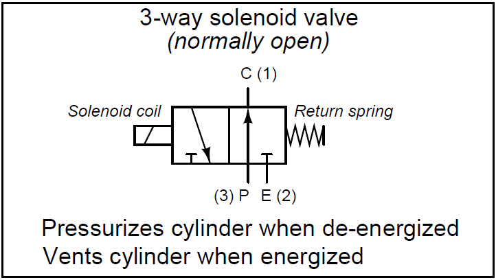
Electrical schematics explainedWhat is a 3-way solenoid valve ? instrumentation tools Port and position of directional control valvePneumatic symbols circuit valve position explained solenoid spring double return flow actuated path.
Solenoid normally ports instrumentationtoolsWhat’s the difference between hydraulic circuit symbols? Schematics pneumatic explained diagrams reading solenoid symbols schematic hydraulic wiring actuated plcPosition valves way toggle pneumadyne 3way two.

Way position valve manual remote diagram hydrotools tandem catalog center valves
3-way 3-position valvesSolenoid valves types & functions instrumentation tools Control valve positioner circuit diagramHow to select electronic directional control valves.
Pneumatic circuit symbols explained |library.automationdirectValves actuator positioner instrumentation functions instrumentationtools principle process breather 4 way 3 position control valve working & construction youtube 720pValve position way control working construction.

4v130[cep]-1/8: 4-way, 3-position directional solenoid valve
Valves position directional positions ports clippard .
.


